Each JEM-X detector is a microstrip gas chamber with a sensitive geometric area of 500 cm per unit. The gas inside the steel pan-shaped detector vessel is a mixture of xenon (90%) and methane (10%) at 1.5 bar pressure. The incoming photons are absorbed in the xenon gas by photo-electric absorption and the resulting ionization cloud is then amplified in an avalanche of ionizations by the strong electric field near the microstrip anodes. Significant electric charge is picked up on the strip as an electric impulse. The position of the electron avalanche in the direction perpendicular to the strip pattern is measured from the centroid of the avalanche charge. The orthogonal coordinate of an event is obtained from a set of electrodes deposited on the rear surface of the microstrip plate (MSP).
The X-ray window of the detector is composed of a thin (250
m)
beryllium foil which is impermeable to the detector gas but allows a
good transmission of low-energy X-rays (see dashed curve in
Fig. ![[*]](crossref.png) ). the Be window imposes an absolute lower limit of
keV on the energy of X-rays coming into the detector, and
hence it is meaningless to try to push the data analysis below this
limit.
). the Be window imposes an absolute lower limit of
keV on the energy of X-rays coming into the detector, and
hence it is meaningless to try to push the data analysis below this
limit.
 |
A collimator structure with square-shaped cells is placed on top of
the detector entrance window. It gives support to the window against
the internal pressure and, at the same time, limits and defines the
field of view of the detector. The collimator is important for
reducing the count rate caused by the cosmic diffuse X-ray background.
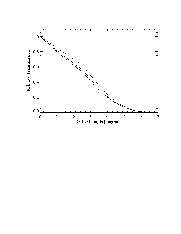
However, the presence of the collimator also means that sources near
the edge of the field of view are attenuated with respect to on-axis
sources (see Fig.). The materials for the collimator
(molybdenum, copper, aluminium) have been selected in order to
minimize the detector background caused by K fluorescence. Four
radioactive sources are embedded in each detector collimator in order
to calibrate the energy response of the JEM-X detectors in orbit. For
JEM-X1 two
Fe and two
Cd sources were used. For JEM-X2
all four radioactive sources are
Cd. Each source illuminates
a well defined spot on the microstrip plate.
Cd emits 22 keV
and 88 keV photons.
Fe produces one unresolved doublet at 6
keV. The gain of
the detector gas is monitored continuously with the help of these
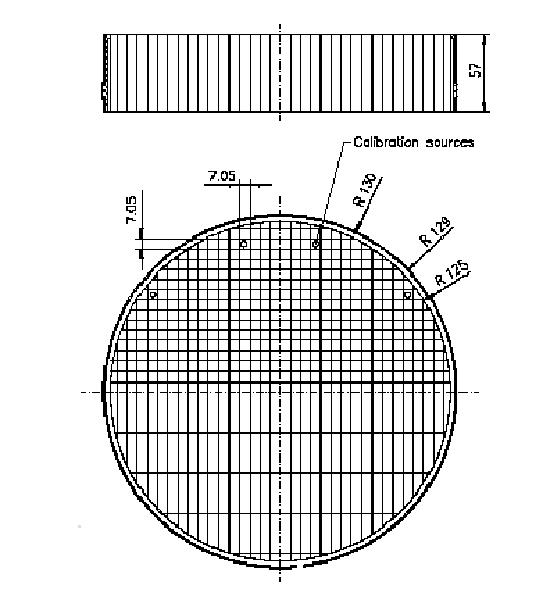
sources. Figure shows the collimator layout and the
locations of the calibration sources. There is one calibration source
for each anode segment on the MSP.
The 29.6 keV photons produced by Xe fluorescence can be detected
all over the MSP and are used for offline monitoring of the gain
correction by the software, and also to produce instrument model
tables of the spatial gain (SPAG) variation across the detector
plate. For the complete archive of these offline analyses see:
http://outer.space.dtu.dk/users/oxborrow/sdast/GAINresults.html.
 |