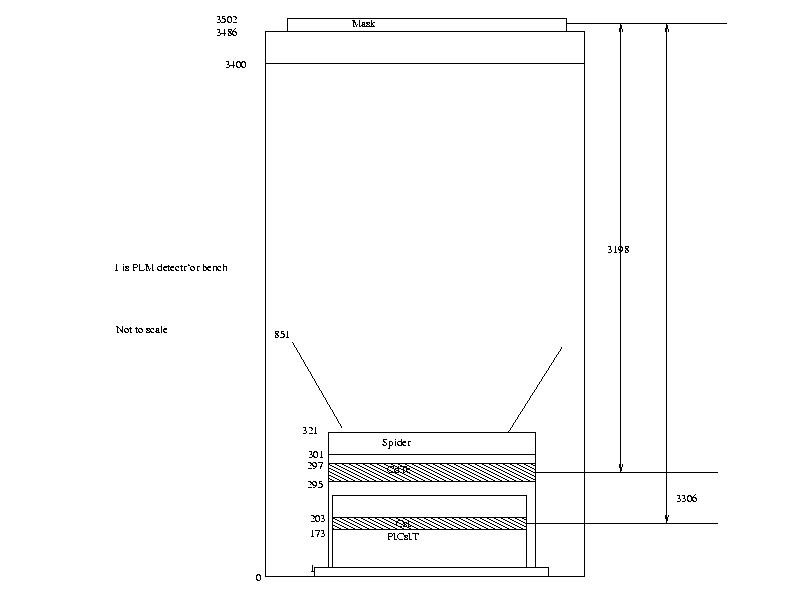
The coded mask is optimized for high angular resolution. As diffraction is negligible at gamma-ray wavelengths, the angular resolution of a coded-mask telescope is limited by the spatial resolution of the detector array. The angular resolution of a coded mask telescope is defined by the ratio between the mask element size (11.2 mm) and the mask-to-detection plane distance (3133 mm).
IBIS is made of a large number of small, fully independent pixels.
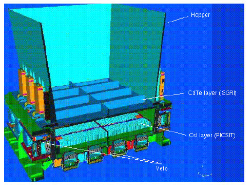
The detector features two layers, ISGRI and PICsIT: the former is made of Cadmium-Telluride (CdTe) solid-state detectors and the latter of Caesium-Iodide (CsI) scintillator crystals. This configuration ensures a good broad-line and continuum sensitivity over the wide spectral range covered by IBIS. The double-layer discrete-element design of IBIS allows the paths of interacting photons to be tracked in 3D if the event involves detection units of both ISGRI and PICsIT. The application of Compton reconstruction algorithms to these types of events (between few hundred keV and few MeV) allows an increase in signal to noise ratio attainable by rejecting those events unlikely to correspond to source photons inside the field of view.
The detector aperture is restricted, in the hard X-ray part of the spectrum, by passive shielding covering the distance between mask and detection plane. An active BGO scintillator VETO system shields the detector bottom as well as the four sides up to the bottom of ISGRI.
Figure ![[*]](crossref.png) shows a cut-away drawing of the various components
of IBIS (except the mask and tube). Fig. shows the distances between
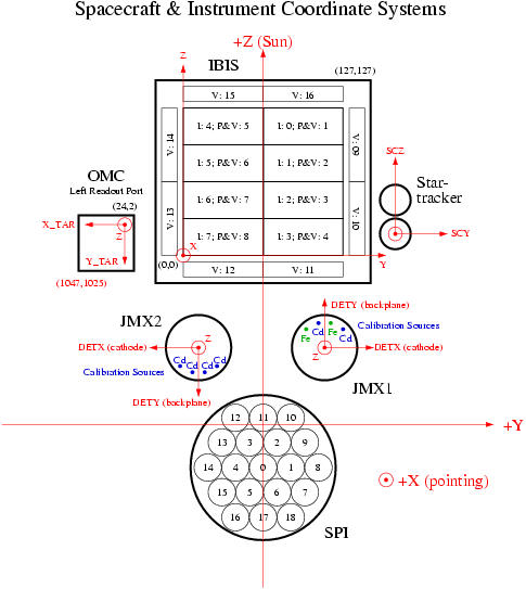
different parts of the detector assembly. Fig. shows the spacecraft & instrumentss coordinate systems.
shows a cut-away drawing of the various components
of IBIS (except the mask and tube). Fig. shows the distances between
different parts of the detector assembly. Fig. shows the spacecraft & instrumentss coordinate systems.
 |
 |